


What Is Visual Measurement on a GNSS Receiver? Non-Contact Point Measuring Explained

The AP50 Vision IMU-RTK GNSS receiver: GNSS, IMU and dual-camera technologies in one unit — the camera pair is what makes non-contact point measuring possible.
Visual measurement lets a GNSS receiver measure points you cannot reach with the pole: aim the built-in cameras at the target, and the receiver computes the point's position from camera geometry plus its own RTK position and IMU attitude. On current APEKS Vision receivers the official specification is a typical accuracy of 2–4 cm within a 2–15 m working range, under normal lighting conditions.
Visual Measurement, Defined
Every GNSS measurement needs the antenna where the point is. For most points that is fine — plant the pole, plunge the tip. But plenty of points are not pole-reachable: a corner across a canal, a bolt head on a busy lane, a feature inside a fence, a spot on a slope you would rather not climb. Traditional answers — offsets, tape pulls, reflectorless total stations — each cost time or a second instrument.
Visual measurement solves this inside the receiver itself. The receiver carries a camera pair; you stand at a safe spot, aim the cameras at the target from two angles, and the instrument computes the target's coordinates non-contact. No walking to the point, no extra prism, no estimating an offset by eye.
It is worth separating two terms you will see in official specifications, because they are different capabilities:
Visual survey — measuring the coordinates of a point you aim at. The official accuracy statement on current APEKS Vision receivers: typical 2–4 cm, range 2–15 m (normal lighting conditions).
Visual stakeout — the reverse: the screen shows where a design point is so you can navigate to a spot you will physically mark. On the same receivers this runs at the receiver's RTK accuracy line, H 8 mm + 1 ppm RMS / V 15 mm + 1 ppm RMS — and it is a close cousin of the AR workflow described in our AR stakeout explainer.
How It Works: Cameras, IMU and RTK in One Chain
Visual measurement is a sensor-fusion result — three layers contribute, and each has its own error budget:
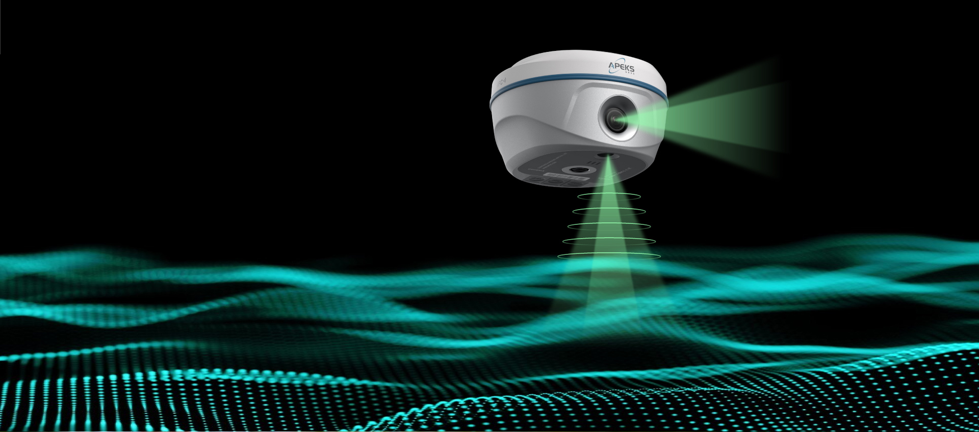
The working concept: the receiver's cameras observe the target while RTK and the IMU anchor the observation in real coordinates.
Visual Measurement vs. Laser Ranging vs. the Pole
Three ways to get a coordinate, each with a different reach-accuracy profile:
| Method | Official accuracy on current models | Reach | Typical use |
|---|---|---|---|
| Pole tip (contact) | RTK H 8 mm + 1 ppm / V 15 mm + 1 ppm RMS | Wherever you can physically stand the pole | Ground points, control, stakeout checks |
| Laser ranging (AP40 Laser+) | Laser survey ±8 mm + 5 mm/m (tilt within 30°); 120 m range | Long reach: facades, water edges, canopy gaps | Hard-to-reach points at distance |
| Visual survey (AP50/AP60) | Typical 2–4 cm, range 2–15 m (normal lighting) | Short range, line-of-sight, no reflection needed | Nearby unreachable points: fences, lanes, slopes |
The three methods are complements, not substitutes — the receiver line covers them all.
Laser ranging deserves its own caution: it is a different tool with a different error model (its accuracy grows with distance, hence the ±5 mm/m term) and a much longer reach. How the two capabilities divide the work is covered in our guide to using laser survey on RTK GNSS receivers.
Where It Fits in Real Work
Cadastral and boundary surveys. Property corners hide under fences, inside hedges, across narrow waterways — exactly the 2–15 m, line-of-sight cases visual measurement was built for. The workflow is the same one documented in our cadastral and boundary survey guide, with the visual measurement replacing the risky walk to the corner.
Ground truth under drone flight lines. Aerial mapping leaves gaps the camera cannot see through: dense canopy, shadowed alleys, water surfaces. A vision receiver fills those gaps at ground level — the division of labor between the drone and the ground unit is described in our AP60 Vision drone-gap complement guide.
Busy or hazardous spots. Traffic lanes, construction edges, unstable slopes: measuring from a safe standing position with cameras beats planting a pole in them, and the 2–4 cm typical accuracy is more than enough for topographic and as-built records at these sites.
Where it does not replace other tools: survey-grade control and stakeout marking still belong to the RTK pole line (8 mm + 1 ppm class), and long-distance reaches belong to the laser. Visual measurement owns the short-range, line-of-sight, non-contact band between them.

Aiming at a structure: the target view locks the feature, and the receiver resolves its coordinates from the camera geometry.
The AP50: The Vision Receiver in the APEKS Line
The APEKS AP50 Vision IMU-RTK GNSS receiver is the model that carries the visual measurement capability in the current APEKS line. Official specifications, verbatim from the product page:
Positioning. 1408 channels tracking GPS, GLONASS, Galileo, BDS, QZSS, NavIC and SBAS; RTK H 8 mm + 1 ppm RMS / V 15 mm + 1 ppm RMS with initialization under 5 s typical and over 99.9% reliability; PPK H 2.5 mm + 0.5 ppm / V 5 mm + 0.5 ppm RMS. Visual survey: typical 2–4 cm, range 2–15 m (normal lighting conditions). Visual stakeout: H 8 mm + 1 ppm RMS / V 15 mm + 1 ppm RMS.
Vision hardware. Two global-shutter cameras (2 MP & 5 MP), 84° field of view, 30 fps. Per the official feature list, the 2 MP front camera achieves visual measurements while the 5 MP bottom camera achieves AR stakeout — one camera pair, two visual workflows.
Field readiness. IMU tilt 0–120° with ≤ 2 cm survey accuracy within 60°; UHF radio 2 W Tx/Rx, 410–470 MHz, 8–15 km working range in ideal environments; internal 7.4 V 7000 mAh Li-ion battery.
AP60 or AP50? The AP60 Vision carries the same visual survey and visual stakeout accuracy lines; how the two models divide the lineup is compared in our AP60 Vision vs AP50 buyer's comparison, and the category cost picture is in the RTK GNSS receiver price guide.

The AP60 Vision: the same visual survey capability (2–4 cm typical, 2–15 m range) in the sibling model.
FAQ
What is visual measurement on a GNSS receiver?
Visual measurement is non-contact point measuring: the receiver's built-in cameras observe a target you aim at, and the instrument computes the target's coordinates from the camera geometry combined with the receiver's RTK position and IMU attitude. It lets you measure points you cannot physically reach with the pole, without a prism or a separate total station.
How accurate is visual measurement?
On current APEKS Vision receivers (AP50, AP60) the official specification is a typical accuracy of 2–4 cm with a working range of 2–15 m, under normal lighting conditions. The conditions matter: stay inside the stated range and lighting window, and treat visual-measured points as topographic-grade rather than control-grade.
Is visual measurement the same as visual stakeout?
No. Visual survey measures the coordinates of an existing point you aim at. Visual stakeout is the reverse — the screen guides you to where a design point is so you can mark it, running at the receiver's RTK accuracy line (H 8 mm + 1 ppm RMS / V 15 mm + 1 ppm RMS on the AP50). Both use the same camera hardware but solve opposite problems.
Should I choose a vision receiver or a laser receiver?
Choose by reach and point type. Vision (AP50/AP60) covers short-range, line-of-sight points within 2–15 m — fences, corners, slopes — at 2–4 cm typical accuracy. Laser (AP40 Laser+, 120 m range) covers long-distance reaches like facades and water edges. Many crews pair one vision or laser rover with a standard RTK rover; send us your typical sites and we will recommend the mix.
Does visual measurement work in bad light or through obstacles?
The official accuracy is specified for normal lighting conditions, so dim light, glare and night work fall outside the stated 2–4 cm window. It also requires line of sight — it does not measure through vegetation, walls or water. For dark or obstructed targets, the laser line or a physical pole measurement is the appropriate tool.
NEED A RECEIVER THAT MEASURES WHAT THE POLE CANNOT?
Tell us your typical sites and unreachable-point scenarios — our team will recommend the vision, laser or standard RTK configuration and send a formal quotation.
Send an Inquiry → WhatsApp Us →About the Author: Marin Hu is a Full-Domain Marketing Expert & Field Engineer at APEKS GNSS, covering GNSS RTK, handheld SLAM LiDAR and total station workflows for international survey projects.